So how’d you safely solve having cables of (widely) varying resistance?
Smartphones already do this. They essentially measure the resistance of the cable by measuring the voltage and correlating it with the current drawn, and regulate the current accordingly.
That would require twice the number of contacts for the same number of physical wires, which would make the plugs even larger.
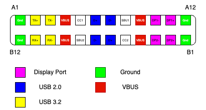
No. Look at the pinout. It's not symmetrical. They could've made it perfectly symmetrical.
>Smartphones already do this. They essentially measure the resistance of the cable by measuring the voltage and correlating it with the current drawn, and regulate the current accordingly.
No! Where did you hear this?
Smartphones usually either rely on type-c pd nowadays or do far less standard Samsung/Apple resistor on usb line check.
Some power banks also do terrible thing where they increase current pull until they see voltage starting to collapse but that’s to check for OC limits on load switch. However that’s really starting to go away because type c just works
It's been common for many years. Look for a document titled "Mediatek Pump Express Introduction". Another useful phrase to search for more information: "cable impedance detection". Apparently several patents on it too.
"Do cable imp. Calculation. Protect cable from burnout" on page 12
"Adjust Vbus according to cable impedance/quality" on page 14
and "Cable Impedance Measurement" on page 15?
Pump Express is their fast charging protocol, but even before that, in the days of feature phones, they were already doing the measurements and adjusting charging current.
> Smartphones already do this. They essentially measure the resistance of the cable by measuring the voltage and correlating it with the current drawn, and regulate the current accordingly.
Not sufficient. It’s easy to have a cable where the long conductors can safely carry a lot more current than the terminations. Or one could have a 1 foot thin cable connected in series with a 10 foot thick cable.
For that matter, a short low-ampacity cable would look just like a long high-ampacity cable.
It's not resistance per se that you care about, it's how much the cable is heating up which is mostly dependent on resistance per meter.
Imagine 2 cables with the same resistance, one 0.5m long and the other 2m. At a set amount of amps, the 0.5m long cable would need to safely dissipate 4 times as much heat than the 2m cable over the same distance. And you don't know how long the cable actually is (and they make 10cm usb cables after all) so you can't make any decision based on resistance that doesn't risk some cables going up in flames.
Fortunately copper and aluminium, the two most common metals for cables, have resistance that increases with temperature.
Ultimately what I'm saying is that the endpoints have or can measure all the information they need to adapt, and this is even more accurate than requiring a cable to self-identify which is worthless if it's lying (and that can happen unintentionally if it's damaged or the connector is worn.)
Yes resistance goes up the warmer the cable gets, but you know neither the resistance of the cable at 20°C nor the temperature of the cable. Simple example, say the user is charging their phone, you detect the cable getting plugged in and measure the resistance at say 1 Ohm to make the numbers nice. Cool, now at what resistance do you determine the cable is too hot and reduce the current? Copper's temperature coefficient is about 0.4% per °C so the resistance should be 1.12 Ohm at a safe 30°C increase right?
Wrong! The cable resistance you measured could already have been at 50° and you're now pushing the cable into fire hazard territory. This isn't theoretical either, people plug in different devices after another all the time (this also eliminates any sort of memorizing if you were thinking about that). So what are you just going to wait 5 minutes at safe charging current and see if the temperature goes down? That's not going to fly in a market where some devices charge 50% in like 20 minutes.
And all of this is ignoring another important design goal of usb-c: dumb charge-only devices exist and should continue to function with a minimal of extra added components. USB-C allows this with the addition of two simple resistors that set the current you want. Measuring resistance on the other hand either requires a accurate voltage source on the device side (expensive) or somehow connecting the power line to some other line (how that would work without additional control electronics I have no idea).
The copper and aluminum will not become resistive enough to make a difference at temperatures low enough to prevent the rest of the cable from becoming crispy.
I've had a phone like this - it'd increase current until voltage start to sag. It was horrible. Never again.
The difference between high-current and low-current cable was very small, so once cable got a little bit worn out, the detection was basically random. You plug cable, and get 1A charge. Unplug-replug, and it's 0.5A now. Unplug-replug and it gets 2A.
I am very glad that the system has died out and we have cables that simply report their capacity directly.
(that said yes, it could have been simpler, like having a symmetric pinout. But this would be a marginal improvement at best, as USB-IF seems to be incapable of producing simple designs. It'd still be thousands of pages of docs)
I don't think it is possible to have "good implementation" of cable impedance sensing, given the inherent properties of the connectors. Wetting current is a thing, after all, and it can be quite big for work connectors.
Cable-reported capacity does not really change over cable lifetime - the currents used to sense resistance are miniscule, and would not be affected by cable being worn. For example, extra 0.5 ohm of cable resistance completely ruins the current sensing, but make absolutely no difference when measuring 5K or 1K resistance.
And if manufacturer is lying, that's annoying but it's 100% deterministic - you know the cable is bad, you can throw it away. With impedance sensing, the same cable can be good or bad, depending on the mood, and that's why it should not be used ever.
Smartphones already do this. They essentially measure the resistance of the cable by measuring the voltage and correlating it with the current drawn, and regulate the current accordingly.
That would require twice the number of contacts for the same number of physical wires, which would make the plugs even larger.
No. Look at the pinout. It's not symmetrical. They could've made it perfectly symmetrical.